Vision-Based Gap Measurement System
Automated, non-contact elongation monitoring for HTS wire stressing — ArUco marker vision with Modbus TCP PLC integration, replacing manual scale and vernier checks in the tension zone.
Automated Wire Extension Verification
During PSC sleeper production, HTS plain wire (IS: 1785 Part-I, IS: 6006) is tensioned between a fixed bench and movable anchor plate. This system tracks ArUco reference markers on both plates and reports bench–anchor gap in millimetres — supporting IRS-T-39 clause 4.2 elongation verification without entering the high-tension zone.
How It Works
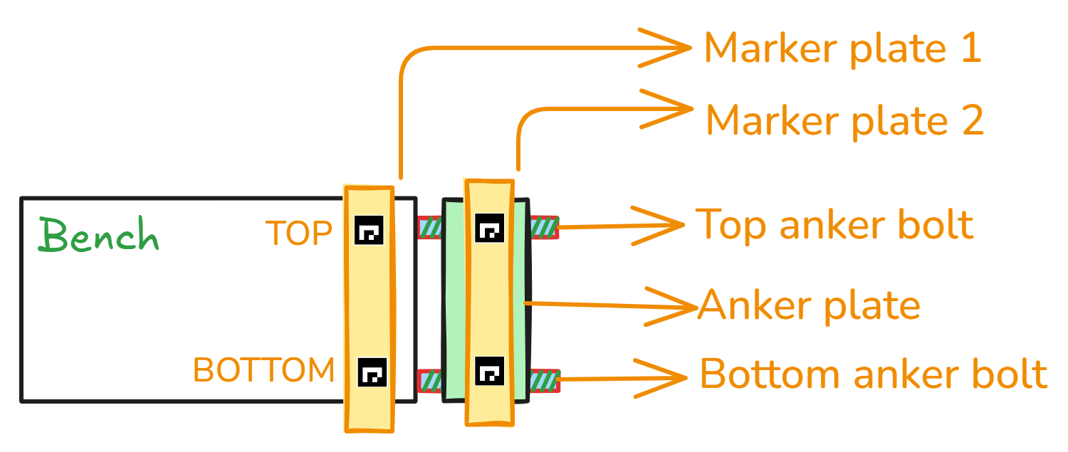
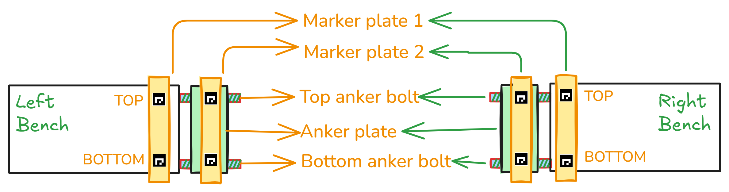
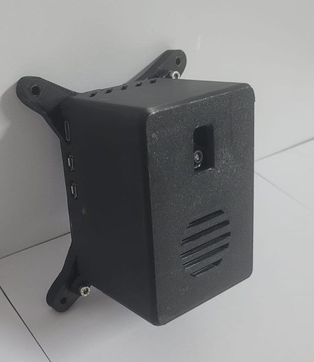
Each bench side has one compact vision device monitoring Marker Plate 1 (bench frame) and Marker Plate 2 (anchor plate). Four ArUco markers per side — top and bottom on each plate — align with anchor bolt positions. Gap readings, fault codes, and heartbeat feed a single stressing PLC for closed-loop control and per-cycle traceability.
ArUco Marker Layout
After hydraulic pull, anchor bolts hold prestress in the wire. Vision measures elongation between fixed and moving marker plates — operators confirm stretch from outside the tension zone.
Factory-Tested on Stressing Benches
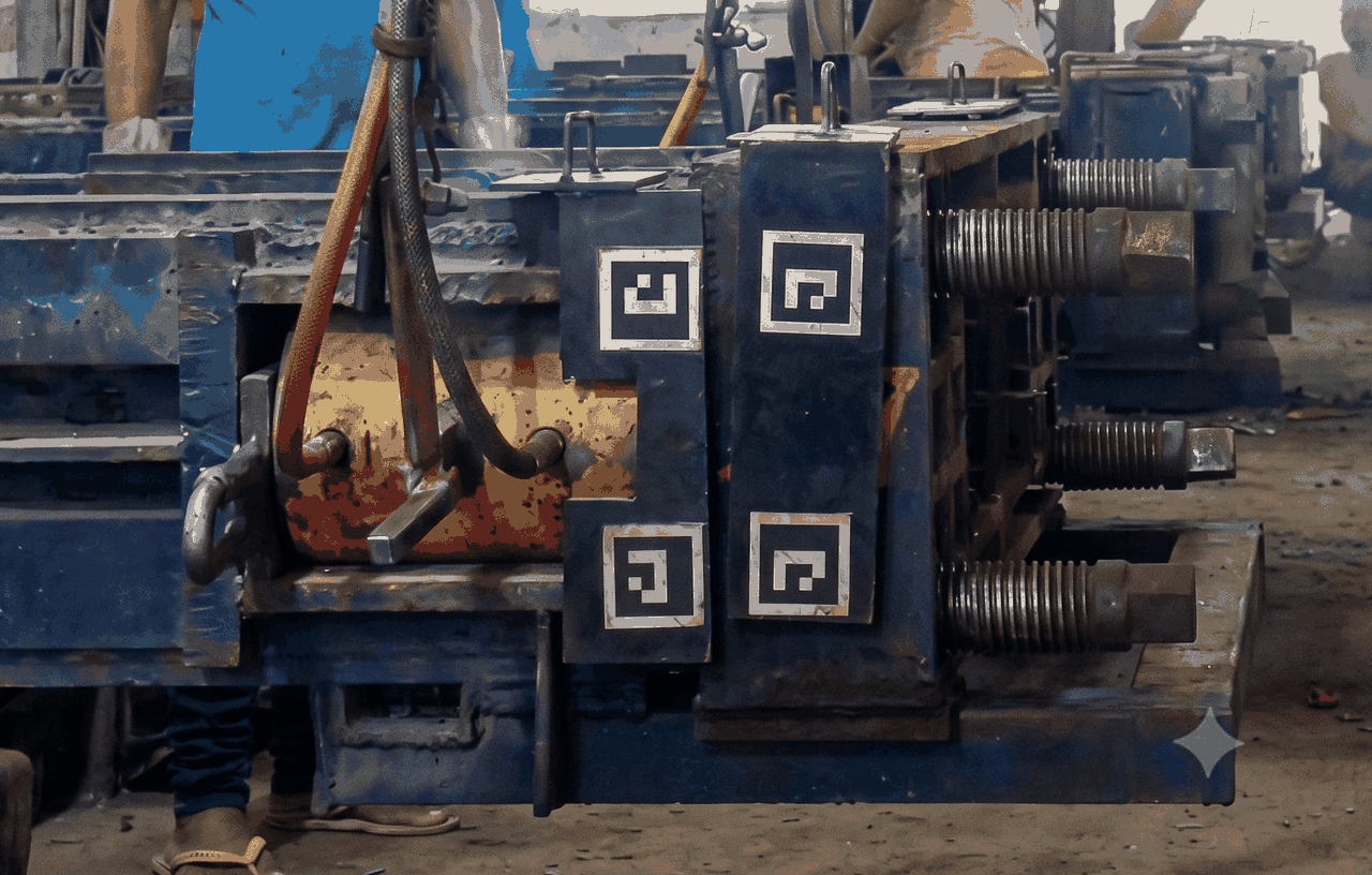
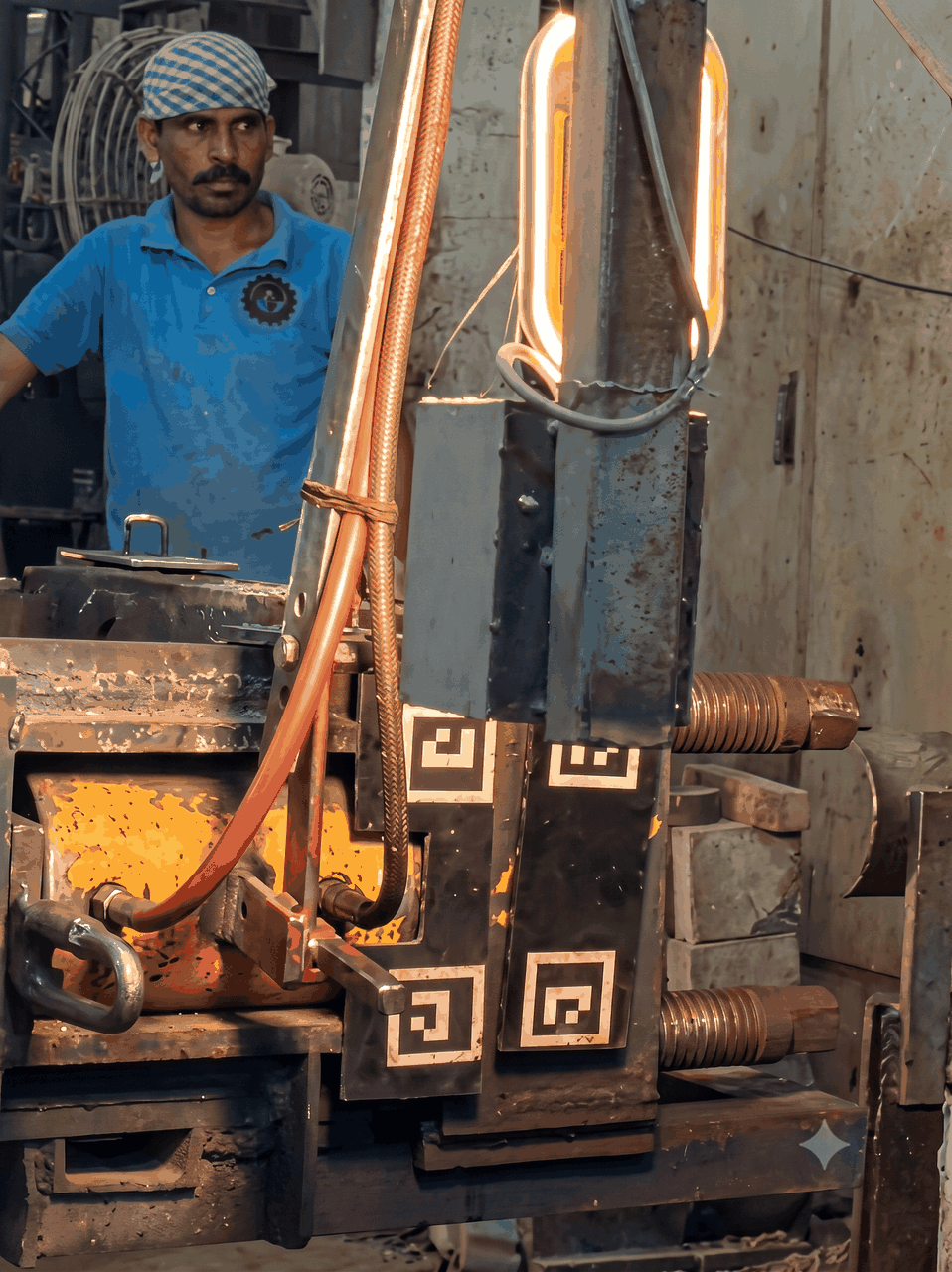
Marker plates and vision devices were fitted during live plant trials. Photos show markers on the bench assembly and the camera view under factory lighting.
Vision vs Laser — Automated Comparison
Both methods are movable — placed on bench arrival and removed after stressing. Vision replaces four laser channels with two Modbus devices while improving accuracy and operator verification.
| Factor | Vision (This System) | Laser (Typical Plant) |
|---|---|---|
| Active sensors | 2 devices (1 per side) | 4 laser sensors (2 per side) |
| Practical accuracy | ±0.1–1 mm typical | ±2–5 mm observed |
| Measure during pull | Yes — continuous | Yes — alignment-sensitive |
| PLC connections | 2 × Modbus TCP | 4 × analog / IO-Link |
| Operator verification | Live camera feed | Red spot + LED per sensor |
| Missing target | Fault if marker not found | No image feedback |
Operator Safety
Keeps operators out of the high-tension hazard zone. Remote readings replace steel scale and vernier checks inside the gap.
Production Speed
Meets the 1-second plant cycle limit. Vision measurement runs continuously during stressing — no pull stop required.
Quality & Compliance
Supports IRS-T-39 double control: fixed-load pull with elongation verification, repeatable readings tied to sleeper drawing setpoints.
PLC Integration
Each side reports gap (mm), system fault codes, and safety heartbeat over Modbus TCP. The stressing PLC can interlock on missing markers, uneven left/right stretch, or lost heartbeat before allowing the next cycle.
Bench Team Layout
Two operators (one per side) fit marker plates and handle local duties; one in-charge monitors both sides and PLC alignment. Setup and removal typically take 2–5 seconds per side.